User Interface: Browsing ARCHITEChTUERS building design platform
Posted 09/19/2023 in Education
Browsing a Building Design Platform can be challenging. Here you will learn how we have organized our UI and how to use to move around the project efficiently.
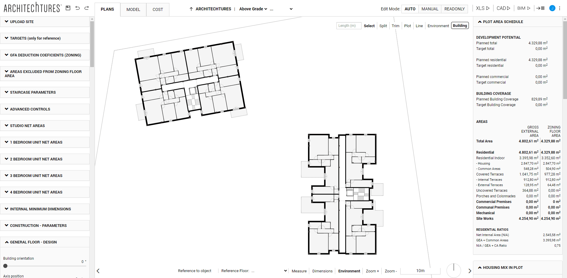
We split our Building Design Platform´s user interface (UI) of the project editor into four areas:
1. The Central Window, is where we view the project and edit its geometry.
2. The Data Panel on the right, is where we view the project metrics in real time.
3. The Input Panel on the left, where you can enter data in an analytical way.
4. The Top Ribbon, to navigate through the project, its views and its editing modes.
First thing to remember is that the first three vary their content according to the level and the editing mode we are in.
For example, if we are at the Unit Level in Auto mode, the central window will show the layout of the house, the input panel will show different design options to customize the apartment, and the data panel will show the apartment´s area schedule, other metrics for that unit and the total estimate. Whereas, if we are at the Floor Level or the Site Level, this content is completely different.
Therefore, we will explain the content of these three elements later. Later we will see them when explaining how each level works in the different editing modes. Instead, if you´d rather see it now go to the Site Planner Section where we start those explanations.
The Top Ribbon
Finally, the top ribbon is the only interface element whose available options are always the same. Regardless of the view mode or the level we are at in the project there is always the same content. Here are the tools necessary to move around the project, its view modes and its editing modes.
From left to right we find the following tools:
File Tools
– Use the diskette icon to save the project on our server.
– Use the backwards arrow to undo the last change made.
– Or the forward arrow to redo the last change undone.
View modes
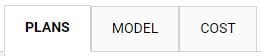
– Plan, this tab changes the view mode to the 2D view mode where we will see the layouts for the project.
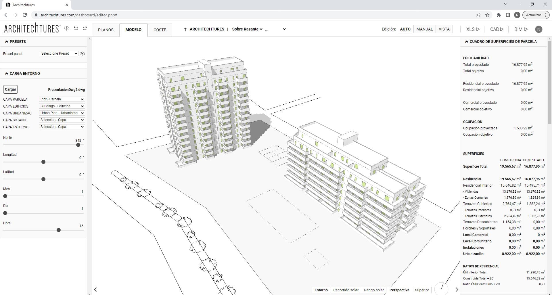
– Model, this tab changes the view mode to the model view mode where we will see the project in 3D.
– Cost, this tab changes the view mode to the estimate view mode where the project costs are described.
Breadcrumb – Moving through your Building Design
Certainly the breadcrumb is the main tool we use to move through the project. It also works more or less the same in any view mode. It has 5 levels:
1st- Root Level.
Firstly, it has the name of the project itself and it takes us to the site planner view if we are in Plan or Model view mode. On the other hand, if we are in the Cost view mode, it takes us to the estimate´s summary where the ratios and the indirect costs of construction are.
2º- Site Planner Level
It has two options: Below or Above Grade. If we are in Plan or Model view mode, it takes us to the basement or site planner view, respectively. On the other hand, if we are in the Cost view mode, it takes us to the estimate for the direct costs of construction of the basements or of all the work above ground, that is to say, of all the buildings above ground and the urbanization of the plot.
3º- Building Design Level
It indicates which building of the project we are looking at. In Model view mode it takes us to the 3D view of that building. On the other hand, in the Plan view mode, it will take us by default to the plan view of the building. Finally in the Cost view mode it takes us to the estimate of that particular building.
4º- Floor Level
It takes us to the view of the selected floor of the building in which we are.
5º- Dwelling Unit Level
Takes us to the view of the house we selected from the floor and building we are in.
At the beginning we will mainly use the breadcrumb to navigate through the project. Later we will use the above-ground and below-ground views to directly access the buildings by clicking on them, as well as the building views to directly enter the houses by clicking on them.
We can go back up one level using the up arrow located just before the breadcrumb. We can also easily change buildings, floors or dwelling units using the breadcrumb itself.
The breadcrumb works just like in a web page or windows explorer. Because our project is also a data structure.
Editing Modes for Building Design
There are four editing modes: Auto, Assisted, Manual and View.
However, the first two are grouped under the first button (Auto). They are also characterised by the fact that they are modes assisted by Artificial Intelligence (AI), which helps us by generating parts of the design.
The editing modes are associated with the phases of the project and we must progress from the Auto mode towards the Manual mode. In this manner we progress from the global to the specific. Never the other way round, because if we go back to a previous phase and edit the project, all the changes made in later phases will be lost.
For example, let’s say I am in Manual mode and I have customised certain apartments to my liking. If I then realise that I have not set the number of floors correctly and go back to Auto mode to correct it, I will lose the changes made in manual mode.
Auto Mode
In Auto mode the project is edited with the variables contained in the input panel. We do not model or create the geometry ourselves. We only give data as a series of variables. The AI then creates a layout for us using this data. In this mode the interactions are always done through the input panel.
Assisted Mode
The Assisted mode is inside the Auto button. Here we edit the geometry of the project and can change specific elements ourselves. These types of changes are always made in the central window. We can perform two types of interactions:
Contour Edits
With these we modify the contours of the units or the position of the core. The AI reacts to our changes by modifying the interior layout of the houses we have changed. Moreover, it will do so using the housing dimensioning criteria we give it.
Configuration via the context menu
In these we change the use of the spaces or customize certain aspects of the core. For example, we can decide on which side of the core the access portal is located. Or whether lifts or stairs should reach the basement or the roof.
Manual Mode
Manual mode is not AI-Assisted. To clarify, at this level the editor behaves like a BIM or CAD modelling program. In order to access it, click on the corresponding button. At this point we will be shown a pop-up warning. It warns that any changes made in manual mode may be lost if we later return to an earlier stage (such as Auto) to edit the project.
Now that we are in this mode we are allowed to completely customise the project to our liking. However, we continue to benefit from a large number of automated processes, such as the automatic generation of:
– Area Schedules
– Dwelling Unit Count
– Efficiency Ratios and other metrics
– Estimates
– BIM Model or CAD files, etc…
View Mode
Finally the View mode disables editing completely. This mode is meant to share the project with clients, engineers, designers,etc… With this purpose in mind we developed the view mode disabling the ability to edit the project.
Building Design Downloadable Files
The downloadable documents are available for both PRO and Business users and consist of:
XLS
Generates a repot in DIN.A4 format with all the metrics of the project, including all the area schedules, housing counts, estimate, ratios, to enumerate just a few. Moreover, it also includes images of the model and the layouts of the whole project.
CAD
Generates all the layout in .DXF format, including plans of all the floors of each building and basement floors and elevations.
BIM
Generates a BIM model in .IFC format, the level of development is approximately LOD 200.
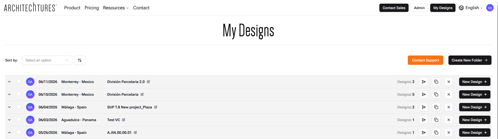
The user icon (the colored ball with the acronym of the user name) allows us to access the drop-down menu of the editor from where we can exit to the dashboard, access our profile, contact technical support or exit the application.