Staggered building design with platforms on imported topography
Posted 05/27/2025 in Technology
Explore how to import a DWG file and use the auto-leveling and platform features in ARCHITEChTURES to design on existing topography, adapting buildings and urban planning to the terrain.
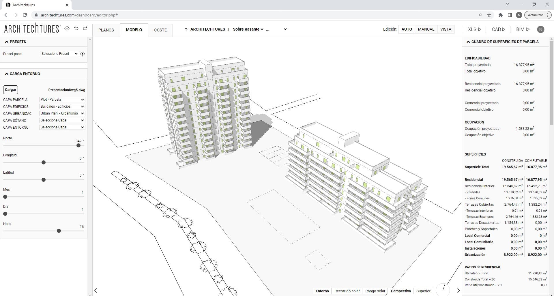
ARCHITEChTURES allows very quick import of DWG files from AutoCAD, including the site and topography. You just need to prepare an AutoCAD file, naming the most important layers, such as plot, building outlines, urbanization, topography, or surroundings.
Once the DWG file is ready, we can load it into árchitechtures, selecting one by one the layers we want to import as a reference to begin working on our project. As you can see, the system recognizes the contour lines of the topography and generates both a solid and a point mesh with the elevations.
In this video, we demonstrate how to use the auto-leveling platforms feature, followed by the manual platform creation functionality.
By clicking the auto-level platforms button located on the upper-right side of the central panel, a menu appears allowing the user to configure several parameters such as the reference elevation, the maximum height for terraced retaining walls, and the cut and fill slope angles. Once these fields are completed, you simply draw the area of intervention. Pressing Enter triggers the automatic grading process based on the specified criteria.
After generating a terraced intervention area, you can revise the parameters at any time by selecting the multi-platform region again. For instance, as shown in the example, you can adjust the maximum wall height or modify the slope angles relative to the platform geometry.
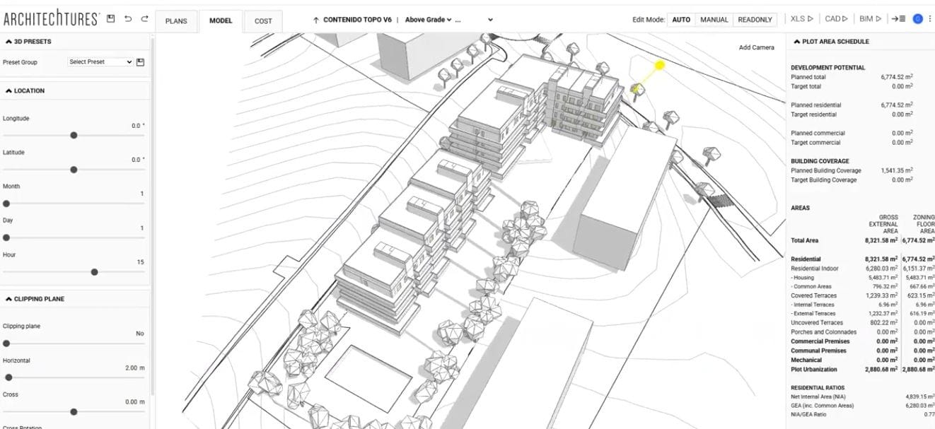
Once the auto-leveling criteria have been defined, buildings can be placed directly onto the modified topography. Each building will automatically align with the designated elevation of its respective platform, as demonstrated in this example.
In addition to the modified terrain and placed buildings, users can design urban landscape elements such as trees, lawn areas, swimming pools, or sports courts. These elements will also adapt their implantation levels automatically to the varying grades across the site.
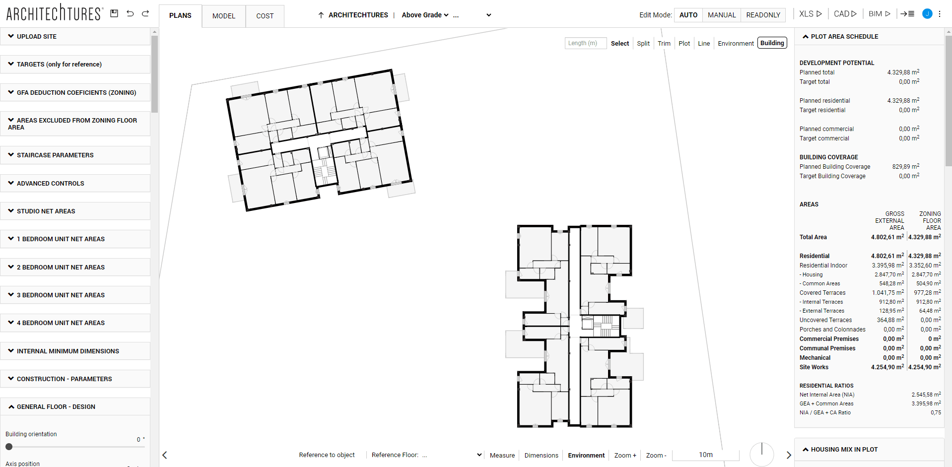
An alternative way to work with topography is by using the Manual Platform Tool, which allows the user to precisely define the platform area and geometry, its elevation, and the associated cut and fill slope angles. Simply click the Platforms button, fill in the three parameter fields, and draw the desired polyline.
In this case, we demonstrate how to create two distinct platforms, each with defined cut and fill angles, on which two buildings with central corridor typologies are positioned.
The system provides real-time feedback on bill of quantities, including earthworks resulting from the modified topography, as well as cut and fill volumes and materials. This enables the user to make design decisions more efficiently, with full awareness of the topographic constraints and their economic implications.
If you haven’t yet explored the auto-leveling and platform functionalities for terrain modeling in ARCHITEChTURES, we encourage you to test them on projects involving sloped sites.