Floorplanner – AI Assisted and Manual Editing Modes
Posted 09/21/2023 in Education
No two projects are the same in Architectures. Therefore, on the one hand, a floorplanner must ultimately allow for full free form customization. However, on the other hand, with Architechtures we are striving to automate the design process. With this in mind we developed the Assisted and Manual modes combining the best of both worlds. To summarize, a succesful floorplanner must automate as much of the design process as possible while allowing for full customization in an intuitive and flexible manner. Read on to learn how you can streamline your design workflow while keeping total control of the end result.
When and how to use Floorplanner in AI-Assisted Mode and Manual Mode
We will switch to the Assisted editing mode once we have finished customizing the project in the Auto editing mode. The Auto editing mode is explained in Section 4. Building – Design.
The editing of the project in Assisted mode is always done through the central window.
Central Window – Navigation
Mouse navigation in the central window in the Building – Floor view is the same as at site level. Similarly, we can access a specific unit or core by hovering over it and double-clicking on it when it becomes shaded in green. It works the same as accessing buildings from the site view.
Context menu
You will see that in addition to the green shading of the house or core, a context menu will show up with configuration options. This is part of the Assisted editing mode and is explained below.
Visualization tools
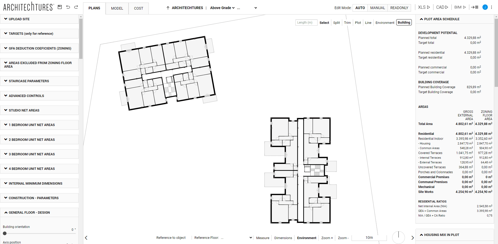
In the Building – Floor plan view (and in the Apartment view) there are two new options in the display tools menu:

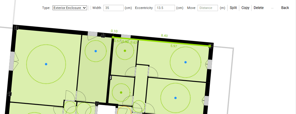
Minimum Dimensions
Displays for each room the inscribed circle of diameter equal to the minimum dimension required for that room type. If the minimum dimension is met, it is shown in green (*). Otherwise, the maximum inscribed circle is shown in yellow or red, depending on the missing dimension. The limit between showing the circle in yellow or red can be customized in the site planner view. In the Input panel, at the bottom, there is the Advanced Controls section.
(*) because by default the limit between showing the circle in green or blue is set to an excess of 10m. This is because normally it is enough to know that the minimum dimension is met. If the user wants to represent a large excess in a different way he can do it by modifying this value in Advanced Controls.
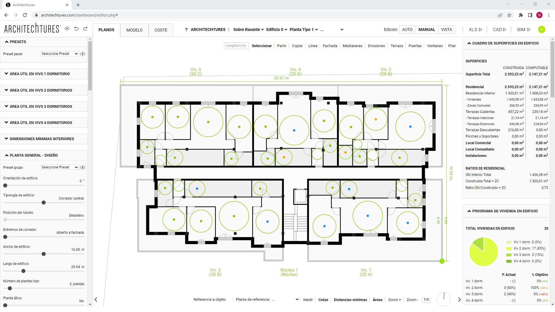
Areas
Represents for each room the relation between the requested area and the actual area with a colored dot. The dot is colored in red or yellow if it lacks too much or too little area. On the other hand, if there is too little or too much area, it is colored in green or blue. The limits between colors can be customized in the Advanced Controls section.
The Floorplanner in Assisted Editing Mode
The Assisted Editing Mode is the second customization phase of the project, the first being the Auto mode. Changes made in Assisted mode can be lost if we go back to Auto mode and trigger a recalculation of the building.
It is perfectly valid to switch between Auto, Assisted and even Manual mode tools, looking for the way to reach the desired solution. But we need to understand when that information will be lost when switching from one mode to another.
Through this exploration we learn the order in which we should customize the building in order to finally do it in the correct order.
We should think of Auto mode as a first approximation that we will later refine. Then using the Assisted mode we can finish shaping it to the exact solution we are looking for.
Contour Edits
This edition mode allows a more fluid design experience and allows the user to modify specific elements of the project. However, it is still assisted by the AI, speeding up the design process.
In Assisted mode we can modify the position and contours of these units by manipulating them directly in the central window. For each unit that has had its outline modified, the AI will recalculate its most optimal interior layout. In doing so, it will take into account the dimensioning criteria previously entered.
The buildings are composed of two types of units, and their configuration options are different:
Access Spaces
These include vertical communication cores, access corridors or portals. Cores can be moved but their outline cannot be modified.
Other Units
These are all other spaces, which are usually mainly dwelling units, but may include other kinds of spaces.
Editing via the context menu
The building spaces have a contextual menu that appears in the upper right corner of the central window when you click on them. The configuration options contained in this menu vary depending on what type of unit it is:
Communication cores
First there is the option on which side of the core the entrance will be placed. Then the controls for access to basement and roof levels of the different elements of the core. If the element name appears in bold it means that the element is enabled and has access to those floors. By clicking on them we can enable or disable them individually.

Other Units
Here we find the use selection menu The current use is highlighted in bold. By default all units are dwellings. However, with this menu we can change their use to create non-residential spaces that usually appear in buildings. For example: spaces for facilities, common areas, commercial premises or empty spaces.

These spaces will appear without internal layout but are fully editable at all levels. Just as if it were another dwelling unit.
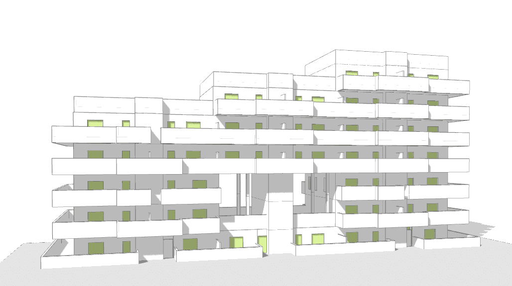
The open spaces deserve a separate mention because they are a powerful tool for customizing the shape of buildings. They can generate porches on the ground floor, covered outdoor spaces on standard floors or uncovered if they are the top floor.
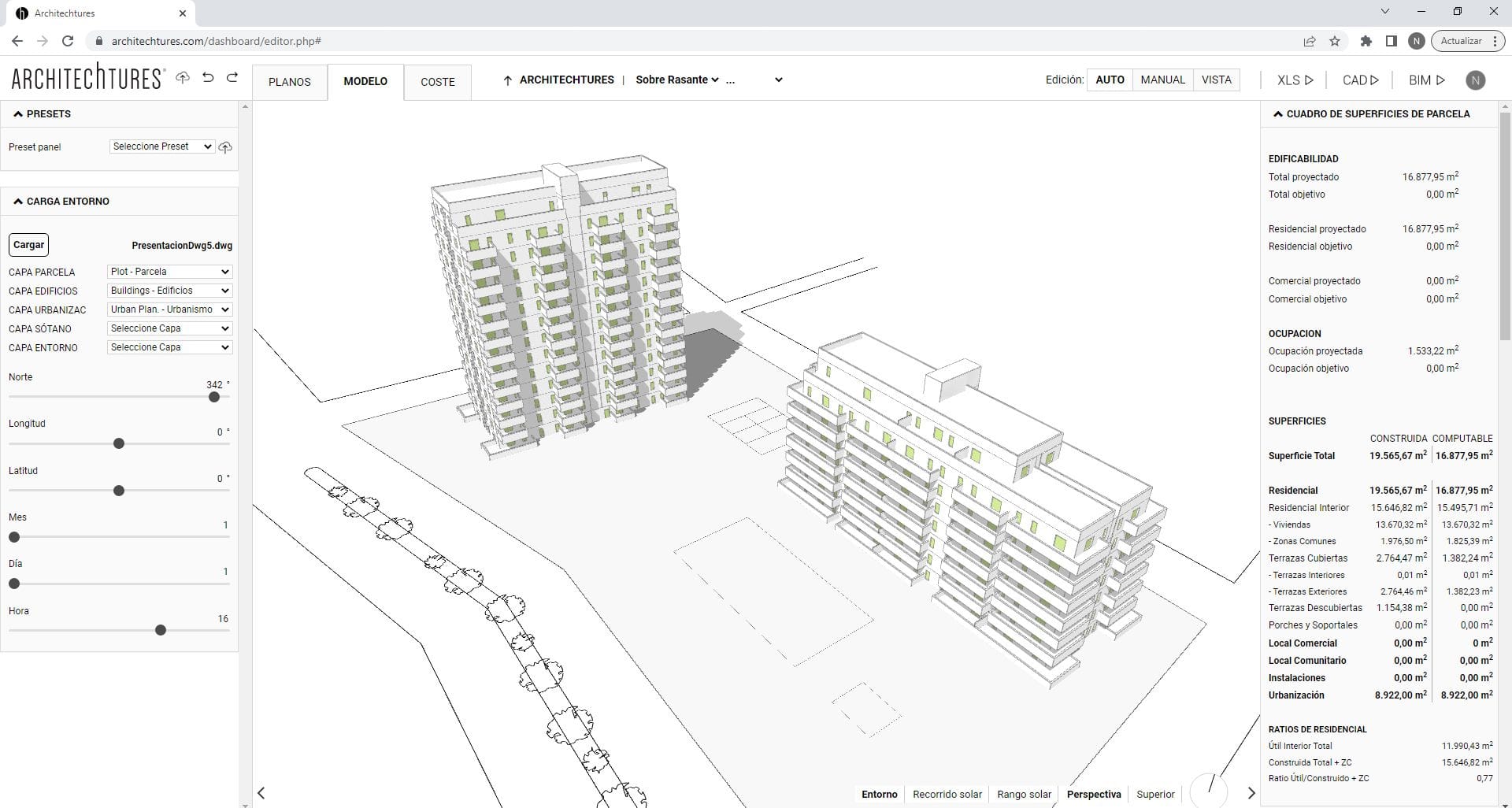
Multi-Storey Mode
In the upper left corner of the central window, in Auto mode, there is a button that controls the Multi-storey edition. When it is highlighted in green, indicating that it is enabled, a dropdown will appear to its right, allowing you to select the floors that will be affected by Multifloor Editing.
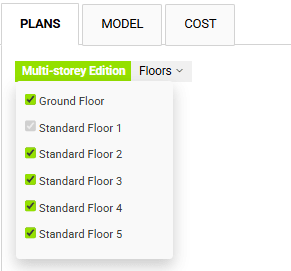
If we click on the Multi-storey edition button, it will no longer be highlighted in green, indicating that it is disabled. While it is disabled, any changes we make will not apply to the other typical floors, but only to the one we are currently working on.
It is worth mentioning that in the Manual editing mode that we will see below there is no Multi-Storey edition button. However, this functionality is instead provided by the Copy function. In addition the Copy function allows us to choose to which floors the changes are copied, giving more flexibility.
Floorplanner in Manual editing mode
The Manual editing mode is the third and last customization phase of the project. In this mode the platform works like a CAD program, allowing us to draw and modify the geometry to our liking. Being a tool meant for the early design stages in the development process, there are some limitations regarding the level of detail achievable. However, it provides other advantages regarding the number of automated processes built into the platform.
We have explained that Auto mode and Assisted mode share the Auto button on the edit mode selector. Manual mode has its own button and it is necessary to use it to access the manual mode.
When the button is pressed, a pop-up appears and must be closed before the project can be edited in Manual mode. It informs us that changes in manual mode are lost if we go back to Auto mode and recalculate the building.
We must keep this in mind when planning the order in which to customize the building. Changes in manual mode must necessarily be the last ones we make.
Select and Drag
The behavior of the manual editing mode is similar to what we saw in the site view. A click on an object selects it and allows us to edit its attributes. A click and drag allows us to modify its position, either by dragging the axis or a vertex.
Manual editing tools
In Manual editing mode, we will see the tools menu in the top right corner of the central window, which will vary depending on the level we are in. Here, we can select the different types of elements we want to create.
-Floor level:
-Unit level:
In the menu there are three Functions: Split, Copy and Block, and three types of Objects, Point, Linear and Nested.
Let’s start with the objects, in the menu we have the tools to create them. In addition, if we select one by clicking on it, the tool menu changes to the edit menu of the element. Here we can see the attributes and methods associated with the type of element.
Types of Objects
Point Objects
Column, which is placed by clicking on a point.
The Delete and Back methods are generic for any element, the first is self-explanatory and the second deselects the element.
The other attributes allow us to modify the dimension or position of the element.
Linear Elements
Line, Facade, Party Walls, Partitions and Terrace, which are placed by defining an axis.
The Move method moves the wall parallel to itself by a given distance (offset).
The Split tool splits the wall at each vertex of other walls on its axis.
The Wall and Width attributes allow us to modify the type of wall and its width.
The Party Walls deserve special mention. They are the only ones that allow us to divide one dwelling from another, or to divide a house from a communication core or an access space such as a communal corridor.
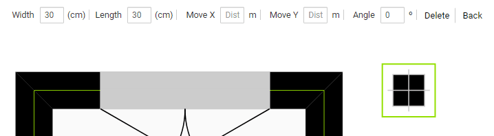
Nested Elements
Doors and Windows
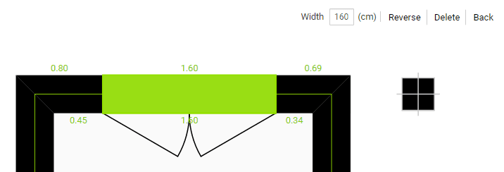
The Reverse method modifies which side a door or window opens from, i.e. whether it is right or left-handed. However, to change to which side of the wall the sash sweeps, we must click and drag the element to the side we want. This capability is also available when the element is initially placed.
The Width attribute allows us to define the size of the element.
Rooms
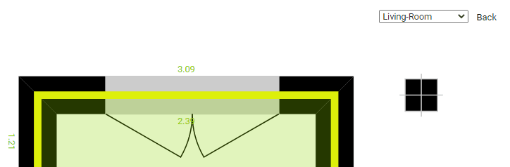
Finally there is a fourth type of element that does not appear in the tools menu, which are the rooms themselves, they do not appear in the menu because their creation is automatic, closing a new space automatically generates a new room that we can select to edit its only attribute, the type of room it is.
Split
The Split function divides a linear element in two at the selected point.
Copy
The Copy function has two modes:
Building
It will convert the currently selected building into an exact copy of the other selected building.
Floor
Will convert the currently selected floor into an exact copy of the other selected floor.
Block
A dropdown menu will open where we can select which elements we want to lock to prevent their modification.