Overview of the platform
Posted 02/16/2024 in Education
As an initial introduction to the ARCHITEChTURES platform, here you will find a comprehensive overview of the projects dashboard and the editor, describing functions, tools, and possibilities.
Project Dashboard
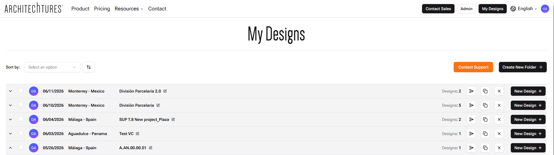
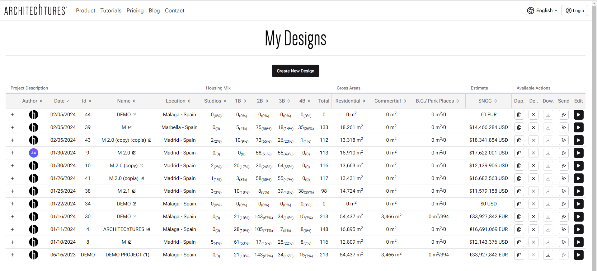
Once you are registered, by clicking on the "My Projects" button in the navigation bar, you will be able to see a summary of all the projects you have completed and an example made by our team.
This area shows a summary of each design: housing mix, areas and estimates.
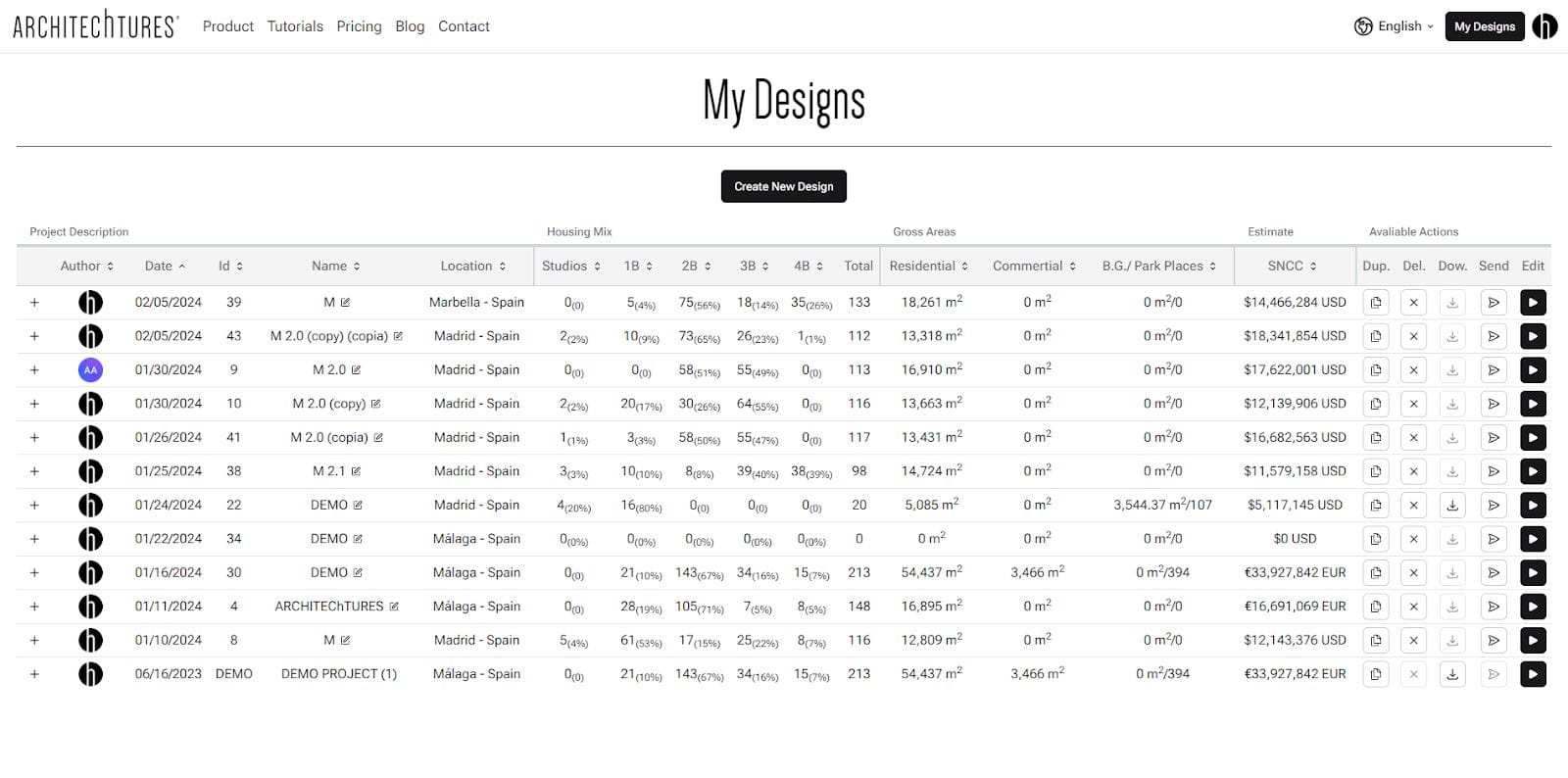
The available actions are:
At the top of the project list:
- Create New: With the "Create New Design" button highlighted in black, we create a new design by giving it a name and location. After confirming, we will automatically see our new project in the listing.
To the left of each design:
- Clicking on the "+" symbol displays individualized information on the composition of dwellings that each building containing the design has.
To the right of each design:
- Duplicate: Creates a copy of the design to explore different versions.
- Delete: Deletes the design if we have already discarded this version.
- Download: Allows you to download project documents, specifically it is possible to generate documents in IFC (BIM models), DXF (CAD drawings) or XLSX (spreadsheets) format.
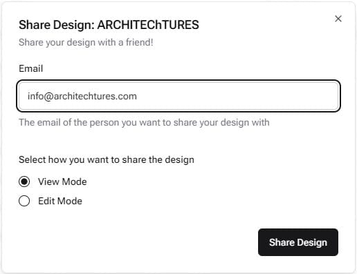
- Send: Allows you to share the design with other users, who do not necessarily have to be paid subscribers, in two different ways by simply entering their e-mail address:
- In View mode (read-only): The project can be viewed, but not edited. It is intended to send a design to a client or other person for them to consult and navigate through it.
- In Edit mode: The project will also be editable by the receiving party, much like sending it by e-mail.
- Edit: The last icon, a black triangle, accesses the Design Editor. This is where 99% of the work will take place.
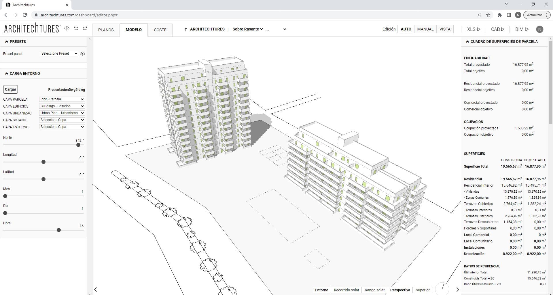
Recognizing the project editor
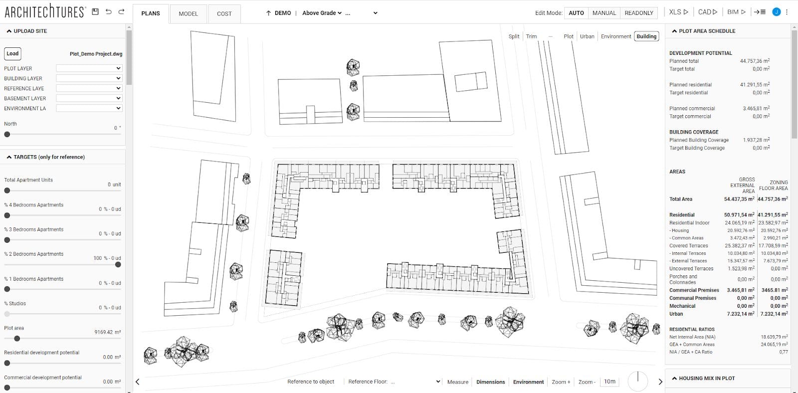
The user interface (UI) of the project editor is structured in four zones:
- The Top Bar, for navigating through the project, its views and its editing modes.
- The Input Panel on the left, where information is entered analytically.
- The Central Window, to view the project and edit its geometry.
- The Data Panel on the right, to view the project metrics in real time.
The last three vary their content depending on the level and the editing mode we are in. For example, if we are at the House Level in Auto mode, the central window will show the floor plan of the house, the input panel will have different design options with which to configure the house, and the data panel will show the table of surfaces, the metrics for that house and the total budget. On the other hand, if we are at the Floor Plan or Site Level, this content is completely different.
Upper bar
The top bar is the only interface element whose available options are always the same. Regardless of the view mode or the level at which you are in the project, the same elements are always located. Here are the tools necessary to move through the project, its view modes and its editing modes.
From left to right we find the following tools:
File Tools
- The floppy disk icon saves the project on our server.
- The back arrow undoes the last change made.
- The forward arrow redoes the last change undone.
View modes
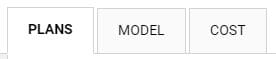
- Plans: to work on the 2D planimetry of the project.
- Model: to work and visualize the project in 3D.
- Cost: to work on the project budget.
Navigation Bar
Certainly the navigation bar is the main tool to move around the project. It also works more or less the same in any view mode. It has 5 levels:
- 1st- Root Level: it is the project name itself and takes us to the site view if we are in Plan or Model view mode. On the other hand, if we are in Cost view mode, it takes us to the budget summary where the ratios and indirect construction costs are detailed.
- 2º- Site Level: we work with all the buildings on the plot. In architectural terms, its natural scale is usually in the order of 1:500 upwards. It is divided into "Above Grade" where the building is created and edited, and "Below Grade" where the basement and its circulation are created and edited optimizing its efficiency.
- 3º- Building Level: indicates which building of the project we are looking at. In Model view mode it takes us to the 3D view of that building. On the other hand, in the Plan view mode it will take us by default to the floor plan view of the building. Finally, in the Cost view mode it takes us to the budget of that particular building.
- 4º- Floor Level: takes us to the view of the floor we select from the building in which we are.
- 5º- Dwelling level: takes us to the view of the dwelling we selected from the floor and building in which we are.
In this way, the navigation bar not only lets us move through the project but also shows which level we are currently working on.
To access the basement, you must explicitly select the "below ground" view in the navigation bar. However, to move between buildings in the "above ground" view, you can follow this sequence:
From the site level, click on a building to automatically center and select it, moving to the building level. At this level, click again on the building to move to the floor level. Then, click on a housing unit once to select it, and a second time to enter the housing unit level.
You can move back up one level using the upward arrow just before the navigation bar. You can also switch buildings, floors, or units directly using the navigation bar itself.
In summary, the navigation bar works much like a web browser or the Windows Explorer, since the project itself is a structured data hierarchy.
Editing Modes
There are four editing modes: Auto, Assisted, Manual and View.
However, the first two are grouped under the first button (Auto) and are characterized by being modes assisted by Artificial Intelligence (AI), which helps us by generating parts of the design.
The editing modes are associated with the phases of concretion of the project and we must progress from the Auto mode to the Manual mode; that is, we progress from the global to the specific. Never the other way around, because if we go back to a previous phase and edit the project, all the changes made in later phases will be lost.
For example: if you are already in Manual mode and, after making changes to customize certain houses, it is detected that the number of floors has not been configured correctly, when you return to Auto mode to correct it, the changes made in manual mode will be lost.
- Auto mode: the project is edited with the variables contained in the input panel. We do not model or create the geometry ourselves; we just give data as a series of variables. Then the AI makes us a project using this data. In this mode the interactions are always done through the input panel.
- Assisted Mode: it is inside the Auto button. Here we edit the geometry of the project and we can change specific elements ourselves. This type of changes are always made in the central window. We can perform the following interactions:
- Shapes edits: Here, we modify the shapes of the apartments or the position of the core. The AI responds to our changes by modifying the interior layout of the apartments we've changed, of course, using the dimensional criteria we provide.
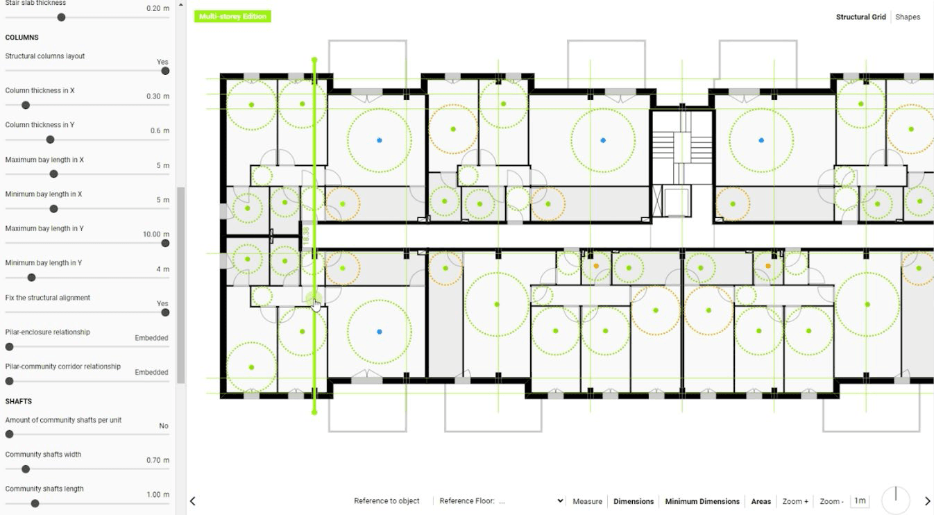
- Structural Grid: here, we will be able to dynamically modify the distribution of the structural frames by moving the axes that are activated when the button is pressed. Additionally, if multi-floor editing is enabled, all changes made will be applied to the other floors, ensuring structural continuity throughout our building.
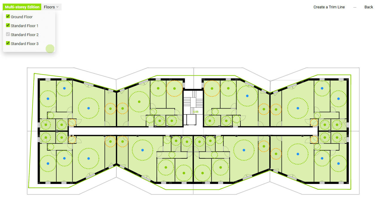
- Trim: With this tool, we can create trim masks for the building, generating different shapes and volume variations. These trim masks can be applied to the floors selected by the user with the "Multi-floor Editing" function.
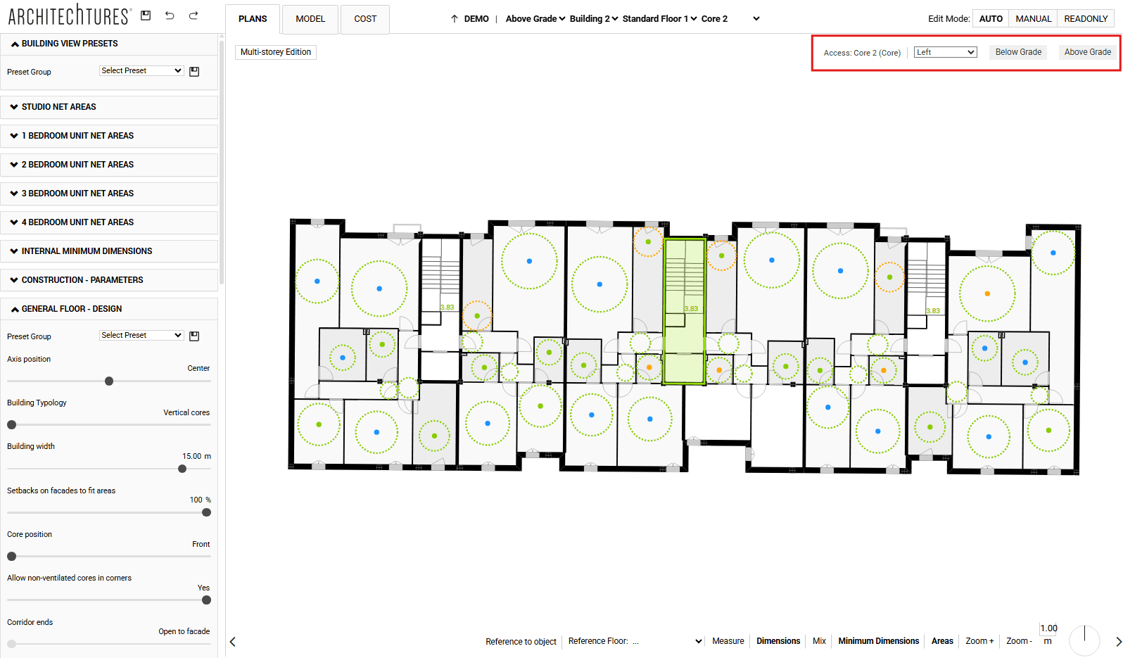
- Configuration through the context menu: in these we change the use of the spaces or configure certain aspects of the core. For example, you can decide on which side of the core the access portal is located; or whether elevators and/or stairs access the basement or the roof.
- Manual mode: it is not assisted by AI. At this level the editor behaves like a BIM or CAD modeling program. To access it we must click on the corresponding button. When doing so, a pop up warning will appear. It warns that any changes made in manual mode may be lost if we later return to an earlier stage (such as Auto) to edit the project.
This mode allows us to completely customize the project to our liking. However, we continue to benefit from a large number of automated processes, such as the automatic generation of: Surface Area Tables, Housing Counts, Efficiency Ratios and other metrics, Budget, BIM model or CAD planimetry, etc...
- Readonly mode: in this mode editing is disabled, it is designed to share the project with other users or third parties that we do not want to have the ability to edit the project, such as customers, engineering companies, structural engineers, etc...
Export modes and others
Generating BIM and CAD is usually a large part of the building design process and can take many hours of work. At Architechtures you can get your BIM or CAD files in minutes, making it easy to get your project documentation process underway. In addition, all our files are created using exactly the same criteria, this reinforces consistency and can be extremely important.
The downloadable documents are available for both PRO and Business users and consist of:
- XLS: generates a DIN.A4 report with all the metrics of the project, including all the tables of surfaces, housing counts, budget, ratios, etc... plus images of the model and the planimetry of the entire project.
- CAD: generates all the planimetry in .DXF format, including plans of all the floors of each building, basement floors and a general floor plan of the project.
- BIM: generates a BIM model in .IFC format, the level of detail is approximately LOD 200.
- The projects icon: formed by an arrow and four horizontal bars, it is a shortcut that redirects the screen to the projects panel.
- The user icon: formed by the colored ball and three vertical dots, it allows us to access the drop-down menu of the editor from where we can exit to the dashboard, access our profile, contact technical support or exit the application.
Input Panel
Located on the left side of the screen, in this panel we enter data in an analytical form. That is, we give information in the form of data such as numbers or texts. This panel is structured in different drop-downs depending on the view mode, level in the navigation bar and editing mode in which we find ourselves; some of the most prominent ones are:
Plans | Root level or site | AUTO mode:
- Unit System: Here we can modify the unit system for our project, switching between the metric decimal system and the imperial unit system, and vice versa.
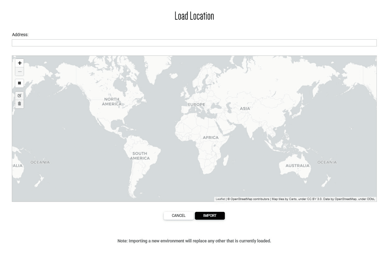
- Upload site: Here we can import a location from OpenStreetMap or load geometric data for use and visualization in the project from .DWG or .DXF files (version 2018 or earlier).
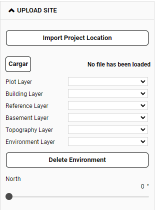
When clicking the “Import Location” button, a pop-up will open with a navigable world map, where we can select a rectangular area up to 8 hectares anywhere in the world. This way, in addition to the built volume, we also import the road network, terrain elevation points to generate the topography, and existing vegetation (based on information from OpenStreetMap).
To load a CAD file, we first use the "Load" button. After explaining the process in a pop-up, a Windows file explorer will open to search for the file and load it. We won’t immediately see any geometry from the loaded file, which is normal—we need to individually call the different layers within the file.
Currently, the import does not support shading, text objects, grouped objects, or blocks, which should be saved exploded.
Depending on which section we load it into, the geometry will be recognized as one type of object or another:
- Plot layer: any closed polyline will be recognized as a plot.
- Building layer: it will be imported as a reference to generate the building.
- Reference Layer: it is used to import any geometric information that we want to use as a visual reference. We can switch from one layer to another but we can only visualize one at a time. Therefore we must group in a single .dwg or .dxf layer all the geometry that we want to visualize at a given time.
- Basement layer: any closed polyline will be recognized as a basement. It will then be used together with the existing buildings to create the basement floor.
- Topography layer: the height of the points and contour lines contained in the layer will be recognized, generating an editable topographic mesh.
- Environment layer: we can load 2D or 3D geometry of the built environment.
- Targets (only for reference): in this section we can define reference data for our project by means of a series of metrics. From this data, we will be indicated how far or close our current project is to the set targets by means of a color code.
- Advanced controls: here we find the controls that regulate the limit between the representation in one color or another. The value of the limit is the value of the difference between the required AI metric and the actual metric obtained in the current design. There are controls for both the area metric and the minimum dimension metric.
- GFA Deduction coefficients (zoning): here we define the percentages used to calculate the computable area from the built-up area according to the use of the space. This affects the computable area calculation that we can see in the tables of the data panel. These coefficients can change according to the urban key of our plot and local regulations, their impact is very important to determine the profitability of a project and therefore it is recommended to check that these coefficients are correctly configured before starting to create buildings.
- Areas excluded from zoning floor area: This section allows us to subtract a certain area per apartment from the computable area. We can define different amounts depending on the type of floor (attic, regular, or ground floor). This option can be useful when considering regulations that allow certain areas to be excluded from the computable area.
Plans | Root level, above ground, Building | AUTO mode:
- Parcel view presets: this is where building presets are generated, managed, and applied at the parcel level.
- Staircase parameters: in this section, global parameters common to all stairs in the building are defined, such as the minimum clear height on the stairs (to ensure compliance with headroom regulations), the height of basement floors, riser height, or tread length (the latter also appears in the building's common area configuration settings).
Modifying the riser height between buildings can cause floor level differences. Therefore, it's recommended to configure these global stair parameters at the beginning, before creating any buildings.
Plans | Root level, above ground, building or floor plan | AUTO mode:
- Building view presets: this is where building presets are generated, managed, and applied at the overall building level.
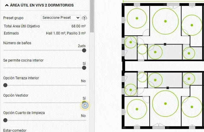
- Net area in: in the useful area sections is where the composition and sizing of the apartments is defined. We have one for each apartment typology, from 0 (studio) to 4 bedrooms. There are two types of configuration options:
- Design Criteria: in these we define which rooms we want to have in the dwelling and some aspects of proximity relationships between rooms, such as the possibility of interior kitchen.
- Target Areas: these define the ideal target area for each room in the house.
- Internal minimum dimensions: these are regulatory requirements the project must meet in terms of geometry. Examples include the diameter of the minimum inscribable circle in the living room or the minimum corridor width. This is where we enter these types of normative-related requirements.
Keep in mind that minimum dimension requirements take precedence over usable area sizing. In case of a conflict, the space will be sized to meet the minimum dimension; for instance, when the area resulting from inscribing the minimum circle is larger than what the user requested.
- Construction - Parameters: here we define globally for the building the thickness of the constructive elements, both vertical and horizontal walls. The configuration of this section has a dramatic impact on the calculation of surface areas and efficiency ratios. It is therefore advisable to set it up immediately after creating the building. It is also very useful to configure our BIM model so that it is easy for us to progress to a higher definition. Therefore, if we are going to request the download of a BIM model it is important to make sure that this section is correctly configured.
- General floor - Design: most of the configuration options in this section can be grouped into two categories:
- Building typology selection: building typology, core position or corridor ends. They define the building typology and the sub-variety that the IA will use to distribute the dwellings.
- Building dimensioning: such as width and length of the building, number of standard floors, floor heights (ground, upper, elevator overrun), or whether to include a penthouse floor.
- Housing mix: in this section, we define the target housing mix for the typical floors. For each apartment type (studio to 4-bedroom), we can set a target distribution percentage.
The AI will try to adhere to this percentage as much as possible within the geometric constraints. The resulting number of units may not be a perfect multiple of the desired distribution.
So, think of the housing distribution as a guiding principle. It’s an interactive process that can be fine-tuned based on the results. This applies not only to the typical floor but especially when considering the whole building. Lower and upper floors often have different layouts due to their unique characteristics. We often adjust the typical floor layout with these variations in mind.
- Common areas dimensions: here are the configuration options of the common areas, the vertical communication core, stairs and elevators. Aspects such as the number of elevators, the stair sectorization or if split landings are allowed, the minimum widths of the community corridors or the access portals to the building, the width of the stair flights, the width and length of the elevator shaft, etc.
- Terraces - General floor: here there are different configuration options, such as minimum width of passage to outside terrace, minimum width of terrace or flight dimension. We can also enable or disable the existence of terraces for each of the facades of the building.
- Exterior enclosure - Parameters: in this section we define globally for the building the size of the openings according to the room they are in. This is done by setting two elements per room: the height of the sill and the width of the window. This can be useful to ensure compliance with certain regulatory requirements, particularly lighting and ventilation requirements.
Plans | Specific Floor Plans | AUTO Mode:
There are certain sections that do not appear in the standard floor plan view which is the default view of a building. Their content refers specifically to specific floors and to configure them we must go to the floor in question. Once there we can see these configuration options and how the changes take effect.
- Gardens - Ground floor: similar to the section of terraces in standard floor plan but simplified, it allows us to dimension the gardens of the first floor dwellings.
- Housing mix - Penthouse floor: similar to the section on standard floor housing program, it allows us to control the distribution of housing on the attic floor.
- Setbacks - Penthouse floor: allows us to control independently by facade the setbacks that the attic floor must have with respect to the standard floors.
- Terraces - Penthouse floor: similar to the section of terraces in standard floor but simplified, it allows us to dimension the terraces of the attic floor.
Plans - Apartment level - AUTO mode:
- Housing view presets: this section allows the generation, management, and application of dwelling presets.
- Design Criteria - Apartment: in this section you can configure design aspects and target areas for a specific dwelling or dwelling type.
Plans | Below grade or basement floor | AUTO mode:
- Plot - Basement floor: here we can specify the dimensions of the main elements located below ground level. From the number of basement floors, perimeter type, structural span, pillar section, road width, parking spaces dimensions, average surface of storage rooms, width of basement enclosure, etc.
Model | Root level, above ground or building | AUTO or MANUAL mode:
- 3D Presets: here we can generate, manage, and apply model presets.
- Location: in this section we indicate the location data of the project: longitude and latitude. We can also define a specific date and time to see a simulation of the solar incidence in our project.
- Clipping Plane: here we configure the parameters to display sections on the model of our projects.
Cost | Root level or location | AUTO or MANUAL mode:
- Currency: to select the currency in which we want to obtain the budget calculations.
- %SNCC: to indicate what percentage of the project execution budget corresponds to items such as quality assurance, occupational health and safety, waste management and other general conditions; to form the SNCC (subtotal net construction cost).
- %ENCC: to indicate what percentage of the SNCC corresponds to items such as overhead and profit; to form the ENCC (estimated net construction cost).
- %Soft costs: to indicate what percentage of the ENCC correspond to items such as feasibility studies fees, design and inspection fees, escalation, bond and insurance, permits, licenses and others.
Cost | Level above grade or Building | AUTO or MANUAL mode:
In the panel we find numerous sections organized by drop-downs according to the budget chapter to which it belongs; for which, depending on the type of element above ground level, we must indicate the value €/m2, €/lm, €/apartment or €/unit.
These chapters are: site work and landscaping, site works, foundations, structure, exterior enclosures and interior partitions, interior finishes, indoor doors, outdoor windows and doors, glass and glassing, telecommunication systems, heating and hot water system, air conditioning and ventilation systems, electrical and automation systems, plumbing systems and fixtures, drainage piping systems, lighting, conveying systems, thermal and moisture protection, roofing, protection and specialties.
Cost | Below grade | AUTO or MANUAL mode:
Similarly, here we find numerous sections organized by drop-downs according to the budget chapter to which it belongs; for which, depending on the type of element below ground level, we must indicate the value €/m2, €/lm, €/parking space or €/unit.
These chapters are: b/g foundations, b/g structures, b/g interior partitions, b/g finishings, b/g doors, b/g ventilation, b/g electrical and automation system, b/g lighting, b/g conveying system and b/g thermal and moisture protection.
Central Window
Located in the center of the screen, it displays the project in its current state and is where you interact directly with the geometry, creating or selecting elements and configuring them. The different tools that compose the menus vary depending on the view mode, level in the navigation bar and editing mode in which we are:
Navigation tools:
- In Plan view mode: right mouse button to drag the view (pan), left mouse button selects and the wheel controls the zoom level. To access a specific building, house or core just click on it when it is shaded green when hovering over it.
- In Model view mode: The left mouse button controls the camera orientation (orbit), the right mouse button drags the view (pan) and the mouse wheel controls the zoom level.
Editing and creation tools:
They are located in the upper right corner of the Plans view mode, grouped according to whether they are editing or creation tools. For ease of use we have tried to make manual editing similar to programs such as Revit or AutoCAD.
- Root level or Above Grade | AUTO or MANUAL mode:
- Split: we can split a linear element in two by the selected point.
- Trim: we can generate a clipping mask of the building by drawing a closed polyline that cuts its axis.
- Plot: we can draw polylines as we would do in a CAD program, enter length values numerically and we also have available snaps and alignments. When we close the polyline, the tool will recognize it as a plot.
- Urban: we can draw polylines as we would do in a CAD program, enter length values numerically and we also have available snaps and alignments.
- Environment: we can draw polylines as we would do in a CAD program, enter length values numerically and we also have snaps and alignments available. When we close the polyline, the tool will recognize it as a building and, by selecting the area, we can define its height.
- Topography: This button will activate the visualization of the topographic points and their spot height. These points can be moved using the mouse cursor or by specifying a distance along the X and Y axes, which, along with the modification of their spot height, will cause the topographic mesh to be restructured; and consequently, the terrain's contour lines will be adjusted.
- Building: with it we draw polylines that are recognized as building axes and are automatically distributed according to the defined design criteria. Subsequently, by selecting it, we can make specific modifications to the building, both on its dimensions and on its attributes. As soon as we have buildings, the data panel on the right is enabled.
- Floor level | AUTO mode:
- Line: draw polylines for reference (like in CAD), input lengths, and use snaps and alignments.
- Trim: create cut masks on the building, generating volume variations. These can apply to selected floors via “Multi-Floor Editing.”
- Structural Grid: This button will activate the visualization of the different structural axes, allowing the location of all the columns that make up the frame to be modified simultaneously.
- Shapes: this button will enable the visualization of the different outlines that make up the spaces of the floor plan; namely, those of the vertical cores, corridors, housing units, etc. These outlines can be modified, increasing or decreasing their dimensions using the mouse cursor.
- Floor level | MANUAL mode:
- Copy: this function has two modes: Building (will convert the currently selected building into an exact copy of the other selected building) and Floor (will convert the currently selected floor into an exact copy of the other selected floor).
- Block: this function allows you to lock elements to prevent them from being modified or moved.
- Sketch: with it we can draw polylines to use them as references as we would do in a CAD program, enter length values numerically and we also have available snaps and alignments.
- Exterior Enclosure: with it we can create new exterior enclosures, drawing lines as we would do in a CAD program.
- Party wall: with it we can create new party walls, drawing lines as we would do in a CAD program. We can distinguish three types: party wall, terrace separation and party wall with core.
- Terrace: to create terraces manually. These are generated by drawing the perimeter, starting and ending at the axis of a wall.
- Column: with it we can include new columns manually.
- Housing level | MANUAL mode:
- Partitions: with it we can create new interior division walls, drawing lines as we would do in a CAD program. We can distinguish three types: partition, partition in core and separation.
- Door: with it we can include new doors manually.
- Window: with it we can include new windows manually.
- Shaft: with it we can include new shafts manually.
- Root level or Low level flush | AUTO mode:
- Split: divide a linear element at a selected point.
- Crop: with this tool we can create an interior contour in our basement floor, to subtract a certain surface.
- Sketch: draw polylines with snaps and alignments.
- Lane: to manually add interior circulation lanes by drawing their axis.
- Ramp: to manually add a circulation ramp by drawing its axis. These can be interior or exterior.
- Storage room: to add storage spaces in the basement. These can be packages of storage rooms or spaces for installations, or commercial. In any case, we must draw the outline we want it to occupy.
- Boundaru: with this tool we can create the outer contour of our basement floor. We can always edit the contours created in the same way as the rest of the linear elements, dragging its axis and vertices to position it or selecting it to edit it.
- Model | AUTO or MANUAL Mode:
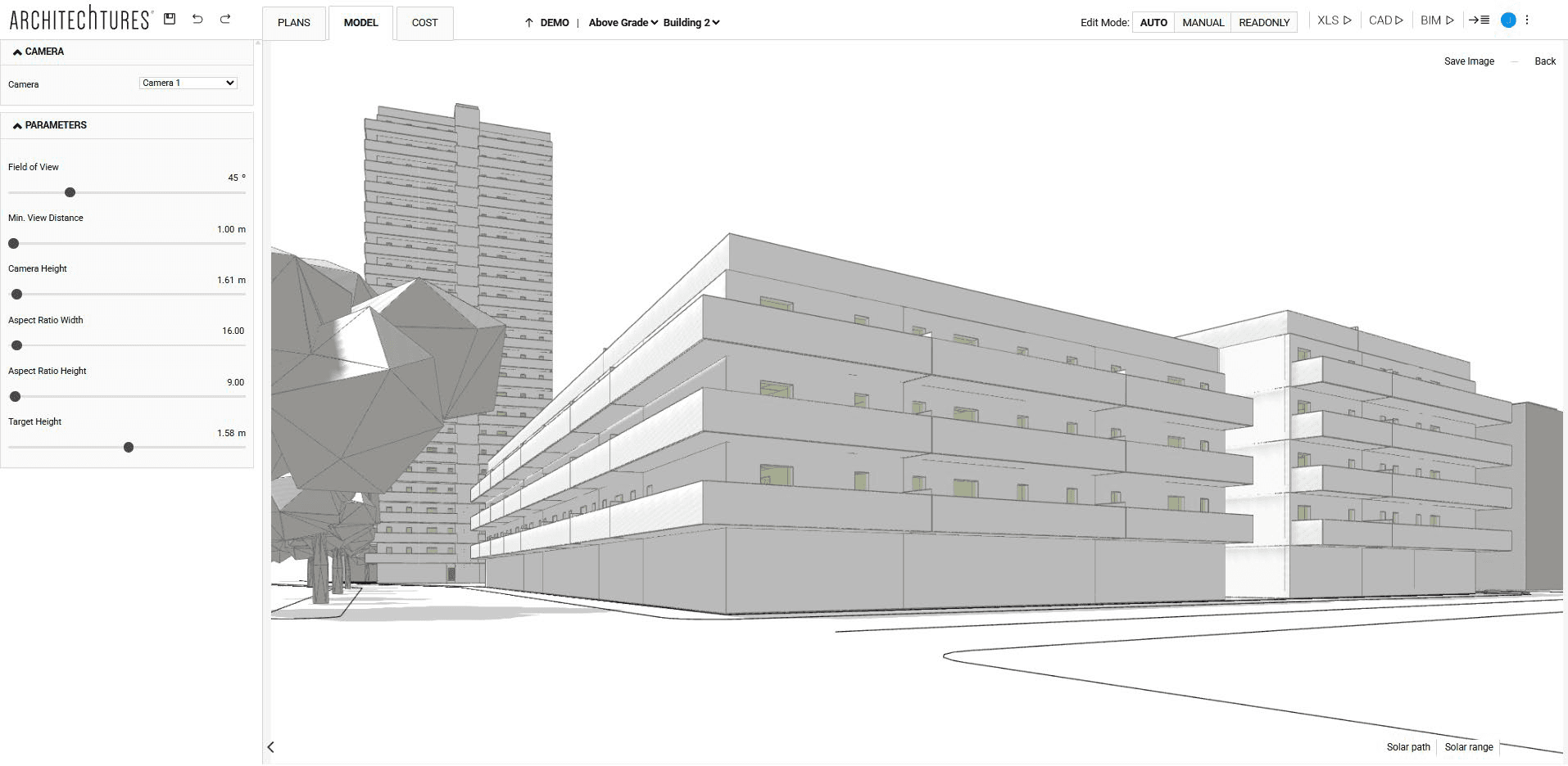
- Add Camera: insert cameras into the model. After setting attributes (height, field of view, aspect ratio, minimum distance), you can download perspective views as .PNG files.
- Other tools:
- Move: with it we can include a distance in meters to move an element in its perpendicular direction.
- Split: we can divide a linear element into parts, according to the intersections it has with other elements.
- Delete: with it we can delete the selected element.
- Back: with it we return to the previous menu.
- Other general functionalities:
In addition to the tools, it is possible to carry out other edits just by using the mouse:
- Dragging existing lines or their nodes, just as we would do in other CAD programs. In this way we can move or rotate a building by manipulating its axis.
- When selecting the axis of a building, clicking on it instead of dragging it, its attributes will appear in the upper right corner of the central window where we can modify them.
- If we have the cursor over a building or some area of it, it is shaded in green color to indicate us that if we click on it we go from the current view to the next one.
Viewing tools:
They are located in the lower right corner.
- Plans | Root level or above grade | AUTO or MANUAL mode:

- Reference to object: allows you to enable or disable snaps and alignments.
- Reference floor: allows you to superimpose the view of another floor on the current view.
- Measure: creates a dimension to measure the distance between two points.
- Dimensions: enables or disables the relevant dimensions according to the view level.
- Mix: Turn the color shading on or off depending on the housing program on the building floor plans.
- Environment: enables or disables the display of the environment elements we have created or imported.
- Zoom (+ and -) : control the zoom level of the view.
- Others: The last items are the graphic scale and the North symbol.
- Plans | Building, floor and house level | AUTO or MANUAL mode:

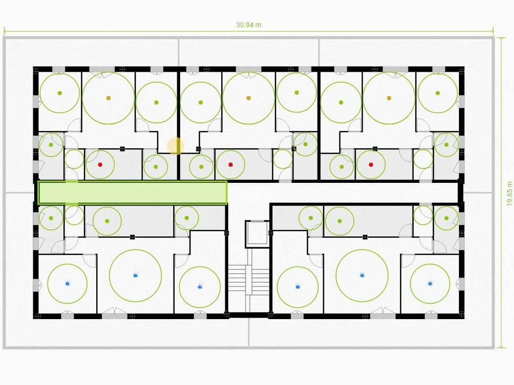
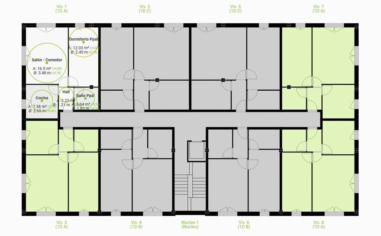
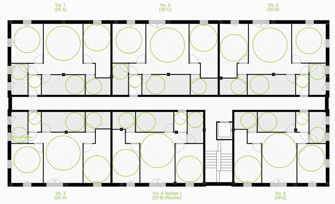
- Minimum dimensions: shows graphically the diameter inscribed in each space of the dwelling, applying a color criterion according to the difference with the minimum dimension required for that type of room.
If the minimum dimension is met, it is represented in green; otherwise, the maximum inscribable circle is represented in yellow or red, depending on how much dimension is missing. The boundary between the representation can be customized in the "advanced controls" section of the input panel, in the location view.
- Areas: shows in the center of each living space, its name, its area and the relation of this area to the "target living areas" defined by the user; that is, it represents for each room the relation between the requested area and the obtained area with a colored dot. The same color criterion is applied as for the "minimum distances".
- Model | Root level, above ground or building | AUTO or MANUAL mode:
- Environment: Enables or disables visualization of the project’s surroundings.
- Cameras: Enables or disables existing cameras in the project.
- Buildings: activate or deactivate the display of existing buildings.
- Solar path and Solar range: enable or disable these displays of the solar position.
- Perspective: is the default view in the model view and is a conical view that the user can control with the mouse.
- Top: is a zenith view of the model that the user can also control with the mouse as he/she would do in Plan view mode.
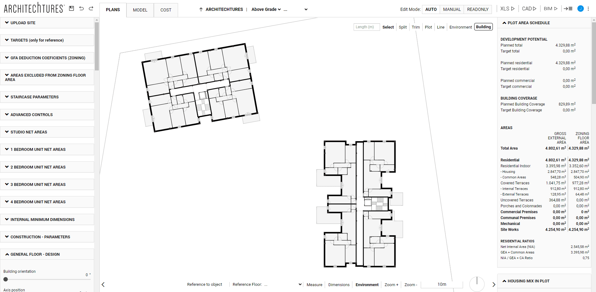
Data Panel
Located to the right of the central window, it shows updated information about the current status of the project. All its metrics are updated in real time for each design interaction.
- Plans or Model | Root level, above grade or below grade | AUTO or MANUAL mode:
- Plot area schedule: includes our objectives for the project, a breakdown of the main areas and the efficiency ratio (Usable / Built + Common areas).
- Housing mix in plot: includes the distribution of housing and an average of the most important areas and ratios by residential typology.
- Below grade areas and ratios: shows the surface areas, units and ratios per dwelling of parking spaces and storage rooms.
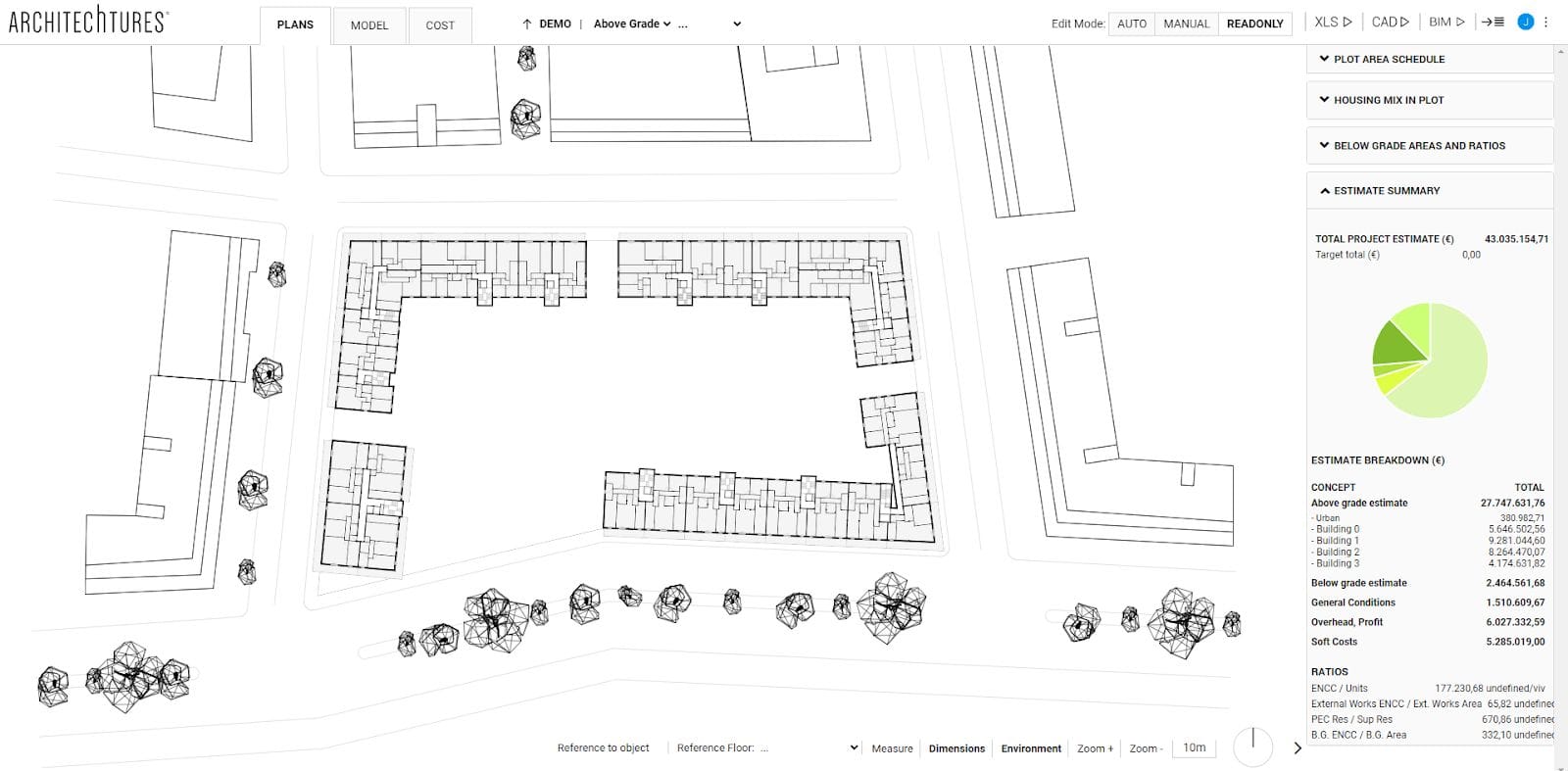
- Estimate summary: shows the budget breakdown with the major concepts and the most relevant ratios.
- Plans or Model | Building level or floor | AUTO or MANUAL mode:
- Building Floor Area Table: has exactly the same format as the plot floor area table, except that only the floor area of the currently selected building is represented.
- Building housing program: shows a total housing count, grouped by number of bedrooms, and comparing the housing distribution obtained in the selected floor with the one required by the user.
- Floor typologies: consists of a list of all the typologies present in the selected floor with their most relevant surfaces and ratios.
- Floor plans | Housing level | AUTO or MANUAL mode:
- Housing Surfaces: includes breakdown of housing surfaces.
If we have entered objectives for the project in the corresponding section of the input panel, in the data panel we will find that objective we have marked, the current status of that metric, and the difference between the two highlighted in a color according to the relationship between them.
Green to indicate that the current state of the metric is exactly as desired or relatively close. Yellow and red to represent that the current state is a little or quite far from the desired state respectively.
TUTORIALS LISTING:
3. Creating our first building with ARCHITEChTURES
4. Deepening the design options
5. Editing modes: Auto and Manual